
Which hand-run procedures should the control system take over? ISA-106 on a GMP site
The water-for-injection (WFI) loop has been drained for a planned maintenance week. On the Sunday night before production restarts, an operator stands at the supervisory screen with a printed procedure of several dozen steps and a pen. Fill the tank, check the vent filter heating, start the pump, open the return, heat, wait, check every return temperature, log the time. Each step is simple. The order matters, the waiting matters, and the person who wrote the procedure retired some time ago.
On the sites we assess, this is where the automation stops. Batch phases run from recipes, loops hold their setpoints, and the operations that happen a few times a year (a utility restart, a changeover, a recovery after a trip) still depend on paper and memory. ISA-106 exists for exactly these procedures. It helps decide which of them the control system should run, how far, and how a good manufacturing practice (GMP) site proves the result.
The procedures that ISA-88 never covered
Pharmaceutical automation engineers know ISA-88, published internationally as IEC 61512-1:1997, the batch control standard behind most recipe systems. It was written for batch processes. A purified water generator, a clean steam generator, a heating, ventilation and air conditioning (HVAC) system or a chilled water plant is not a batch. It runs for weeks, and the risky moments are its transitions: starting, stopping, changing load, recovering from a fault.
ISA-106 is the continuous counterpart. The series has three documents, all listed on the ISA-106 page of ISA: technical report ISA-TR106.00.01-2013 (models and terminology), technical report ISA-TR106.00.02-2017 (work processes) and the standard itself, approved by the American National Standards Institute (ANSI) as ANSI/ISA-106.00.01-2023 and announced in InTech in August 2023.
Its published scope is precise, and worth reading before anyone promises it will cover everything:
- What it covers. Procedures for start-up, shutdown, abnormal situations, hold step and transitions of process feed or output, typically procedures that already exist on paper.
- Where they run. Systems at ISA-95 levels 0 to 2, including the basic process control system (BPCS). Execution at level 3, the operations management layer, is not addressed.
- What it leaves out. Batch operations, manual procedures themselves (their interaction with automated ones is in scope), and procedures implemented inside a safety instrumented system (SIS). The interfaces with an SIS are in scope.
An automated start-up may wait for a permissive from the SIS, but the safety logic stays where it is, under its own lifecycle.
Clean-in-place (CIP) and steam-in-place (SIP) sit on the border. Where they are recipe phases called by a batch system, ISA-88 already structures them. On a standalone skid that serves a continuous utility, or in the abnormal-situation logic around them, the ISA-106 vocabulary fits better. Decide which standard governs which equipment once, in the design philosophy, and write it down.
| Question | ISA-88 (IEC 61512-1) | ISA-106 |
|---|---|---|
| Process type | Batch: a finite quantity made by a recipe | Continuous: transitions of a process that keeps running |
| Typical pharmaceutical use | A granulation, a fermentation, a formulation batch | Restart of a water loop, clean steam start-up, HVAC mode change, utility recovery after a trip |
| What drives the sequence | The control recipe for that batch | A procedure requirement written from the operating procedure |
| Published as | ANSI/ISA-88.00.01-2010 and IEC 61512-1:1997 | ANSI/ISA-106.00.01-2023 and two technical reports |
| Stated limits | Not every batch application, as the IEC abstract itself notes | Batch operations, level 3 execution, procedures inside the SIS |
Three models, read on a CIP skid
The technical report of 2013 describes three models that tie what a procedure must achieve to the equipment it acts on. A standalone CIP skid shows them well, because everyone on a pharmaceutical site has met one.
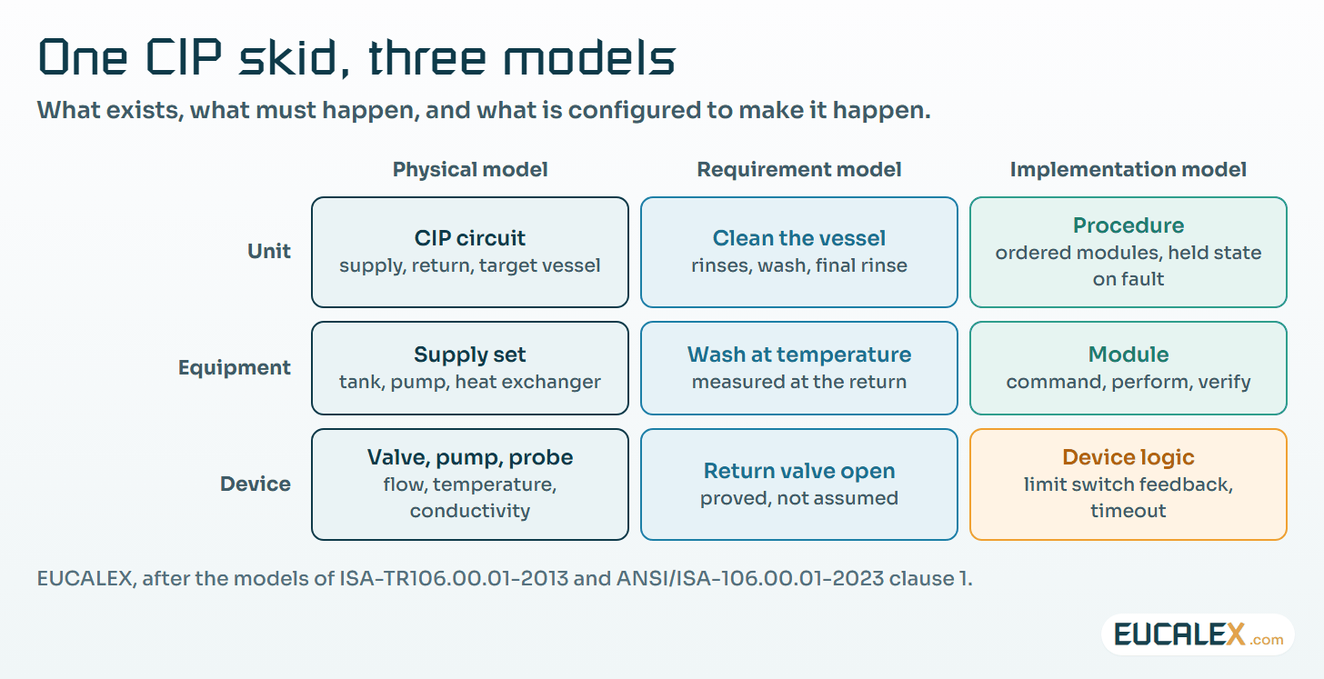
The physical model is the equipment hierarchy most engineers already use, from the site down to a single device. The procedure requirement model states what has to be achieved, at each level of that hierarchy, in process terms: bring the return line to wash temperature, prove the final rinse conductivity. The procedure implementation model is what the engineer actually builds in the controller, and the report allows it to differ in shape from the requirements, as long as every requirement is traced to something that runs.
The building block of the implementation is a module made of three parts: a command that starts it, the actions it performs, and a verification that the requirement was met or failed. That third part is the one paper procedures handle worst. A printed step says “open V-12”; it rarely says how the operator knows the valve really opened, or what to do if it did not.
How far to automate: two styles, and a choice per task
Automating a procedure does not mean removing the operator. The models make room for every degree in between, and the choice can be made task by task. Each command, each action and each verification can stay manual, become a prompt the operator confirms, or run automatically. A typical first step keeps the command manual, automates the actions, and asks the operator to confirm the verification on screen.
The 2023 standard then defines two automation styles, and the names matter because they lead to different designs:
- State-based control (SBC). The unit is always in one defined state, and the logic moves it between states, from start-up to run to shutdown and back to start-up. The standard ties this style to designs where a single module never has several steps active at once.
- Sequence-based control (SqBC). A direct translation of the operating procedure into a sequence of commands that change device states, step after step.
Sequence-based control is quicker to write, and it is often what a site gets when an existing procedure is “put into the controller”. State-based control takes more design work up front. It pays back when the equipment has to recover from faults, because every state knows what is allowed next and what to do when a condition is lost.
Which procedures deserve the effort? On the utilities we review, three criteria do most of the sorting: the procedure is rare enough that nobody is fluent in it, an error in it reaches product quality or equipment integrity, and its steps can be verified by instruments the system already has. A water loop restart meets all three. A filter change that depends on a technician’s hands usually does not.
Designing the held state
Hold step and abnormal situations are named in the scope of the standard, and they are where a GMP site gains most. A paper procedure tends to assume that things go right. When a return temperature does not come up, the operator improvises: waits longer, opens another valve, calls someone. Each improvisation is a deviation waiting to be written.
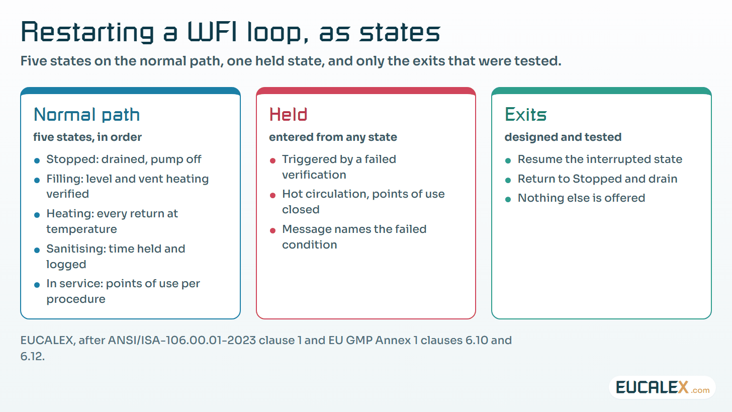
In a state-based design, a failed verification takes the unit to a defined held state. The held state does three things: it puts the equipment somewhere safe for the product and the plant, it tells the operator in plain words which condition failed, and it offers only the exits that were designed and tested. For a water loop, “safe” means circulating hot with the points of use closed, rather than stopping cold.
The texts give the reasons. EU GMP Annex 1 (2022) clause 6.10 gives constant circulation above 70 °C as an example of storing and distributing water for injections so that microbial growth is minimised, and clause 6.12 asks for sanitisation on a predetermined schedule and as a remedial action after out-of-limit results. A held state that drops the loop to ambient on every fault would fight both clauses.
For continuous manufacturing, ICH Q13 (EMA date for coming into effect: 10 July 2023) goes further: section 4.1 asks the dossier for a summary of start-up, shutdown, pause and restart procedures, and section 4.2 asks for site procedures covering start-up, shutdown, pauses and disturbances. A state-based procedure is the simplest way to show they run the same way every time.
Qualifying an automated procedure
An automated procedure is configured logic in a GMP computerised system, qualified like any other function. The difference is where the risk sits: most of the logic runs only on the rare days it is needed, and its fault branches may never run unless someone forces them during testing.
EU GMP Annex 11 clause 4.7 asks for test methods and scenarios that consider parameter limits, data limits and error handling, with documented assessments of any test environment. Annex 15 clause 10.4 asks cleaning validation to consider the level of automation and, for an automatic process, to validate the normal operating range of the utilities and equipment.
That points straight at the hold paths. The requirement model gives the test cases: every verification that can fail is a scenario. The article on tying test depth to risk shows how to keep those scenarios traceable without testing everything at the same depth.
Simulation makes the fault branches testable before the plant is at stake. In InTech, December 2023, Gregory McMillan separates a simple tieback simulation, which he considers may suffice for first-pass testing of sequences and graphics, from the higher-fidelity dynamic models needed to test how control strategies interact with the process. In August 2023 the ISA106 committee announced a technical report on simulation for testing automated procedures and training operators.
| Test stage | What it proves | What it cannot prove |
|---|---|---|
| Logic review against the requirement model | Every requirement has a module with a command, actions and a verification | That the sequence behaves on real equipment |
| Tieback simulation | Order of steps, timeouts, entry into the held state, operator messages | How loops and process dynamics respond during a transition |
| Dynamic simulation | Behaviour through transients: heat-up, pressure changes, interacting loops | Behaviour of the actual valves and instruments |
| FAT on the supplier’s platform | Configuration as delivered, forced faults on simulated inputs | Site utilities, field wiring, real response times |
| SAT and OQ on the plant | Normal path on real equipment, selected hold paths forced safely | Rare combinations not chosen as scenarios |
The qualification stages do not change (the article on what design, installation, operational and performance qualification each prove applies as it is). The user requirement specification (URS) does: a procedure it does not name is never tested on purpose, so a URS that drives the qualification lists the procedures to automate, their style and their held states.
Where to start
- List the rare procedures. Ask the utility and production leads which procedures run fewer than a few times a year and depend on a single experienced person. The list is finished when each line has an owner and a last-run date.
- Write one as requirements. Take the most critical one, often a water or steam restart, and rewrite it in the three parts of a module: command, actions, verification. Add, for each verification, what the equipment must do if it fails. You know it is done when no step says “check” without saying with which instrument.
- Choose the style and the test bench before the code. Decide state-based or sequence-based for that unit, and agree with quality which held states will be forced at the factory acceptance test (FAT) on a simulation, and which at operational qualification (OQ) on the plant.
Five common mistakes
- Automating the paper as it is. The printed procedure contains workarounds and missing verifications. Translating it step by step automates those too.
- A hold that only freezes the sequence. If the equipment keeps doing whatever it was doing, the held state is not safe, only stopped in the code.
- Hold paths never tested. The normal path is tested at every site acceptance test (SAT). The fault branches are the reason to automate, and they are usually the ones with no test record.
- Alarms that ignore the state. A low-temperature alarm during heat-up is noise; the same alarm in service is critical. Alarm settings that do not follow the state train operators to acknowledge without reading.
- Safety logic pulled into the procedure. Interlocks that belong in the SIS end up in the sequence because it was convenient. ISA-106 keeps procedures inside the SIS out of its scope for a reason.
The first procedure to automate is the one nobody on the night shift has run before.
References
- ISA, ISA-106 series of standards: ANSI/ISA-106.00.01-2023, ISA-TR106.00.01-2013, ISA-TR106.00.02-2017.
- ISA, ANSI/ISA-106.00.01-2023, Procedure Automation for Continuous Process Operations, clause 1 Scope (preview), 2023.
- Charley Robinson, ISA-106: New ISA Standard on Procedure Automation for Continuous Process Operations, InTech, August 2023.
- Bill Lydon, ISA-106 in “Influential ISA standards”, InTech, September/October 2020.
- Gregory K. McMillan, Digital Twins for the Virtual Plant, InTech, December 2023.
- European Commission, EudraLex Volume 4, Annex 1, Manufacture of Sterile Medicinal Products, 22 August 2022, clauses 6.10 and 6.12.
- European Commission, EudraLex Volume 4, Annex 11, Computerised Systems, 2011, clause 4.7.
- European Commission, EudraLex Volume 4, Annex 15, Qualification and Validation, 2015, clause 10.4.
- EMA, ICH guideline Q13 on continuous manufacturing of drug substances and drug products, Step 5, 3 March 2023, sections 4.1 and 4.2.
- IEC, IEC 61512-1:1997, Batch control, Part 1: Models and terminology.
Related articles
All articles- DQ, IQ, OQ, PQ: what each qualification stage proves, and what it cannotFrom the quality concept and the URS to the PQ, one question per stage. A plain reference for the engineers and technicians who sign qualification…
- Writing a URS that actually drives the qualification, and deciding whether you need a DQA user requirements specification is either the root of every test that follows or a wish list nobody can test. How to write it one line at a time…
- How deep should a qualification test go? Tie test depth to risk, then prove coverage with a traceability matrixTest scripts multiply until nobody can say what they prove. Three rules bring them back under control: qualify only the functions you use, set the…
EUCALEX
Have a project or a technical challenge?
Contact us: we will be pleased to discuss it with you, with no commitment.
Discuss your project with usStay informed
Receive new EUCALEX articles and technical insights by email.