
The drawing nobody updated: keeping P&IDs and loop diagrams true on a qualified plant
Two in the morning, a utilities corridor next to a formulation suite. A transfer line has to be isolated so a leaking diaphragm valve can be changed before the morning campaign. The technician takes the laminated P&ID out of the panel door, finds the two manual valves upstream, and walks to the spot. There is one valve, not two. Where the second should be, a short spool piece and a flexible hose that someone fitted during a modification and never took away. He calls the shift lead. The shift lead calls the process engineer, who is asleep. The job waits until seven.
Nothing happened that night, and that is the problem with drawings: an out-of-date one does no harm until the day someone trusts it. On a GMP site that day can also be the day of an inspection, when the inspector asks for the P&ID the IQ was signed against and then asks to walk the line.
Three drawings with the same number
Ask a site for “the P&ID” of a system and you will usually get one document number. Behind it there are three different pictures, and most arguments about drawings come from mixing them up.
The as-designed drawing is the approved intent, issued for construction. The as-built is what was actually installed, with the commissioning red-lines drafted back and signed. The as-is is what runs today, after years of repairs, spares and PLC changes. Nobody issues that one: it lives in the field and in people’s heads.
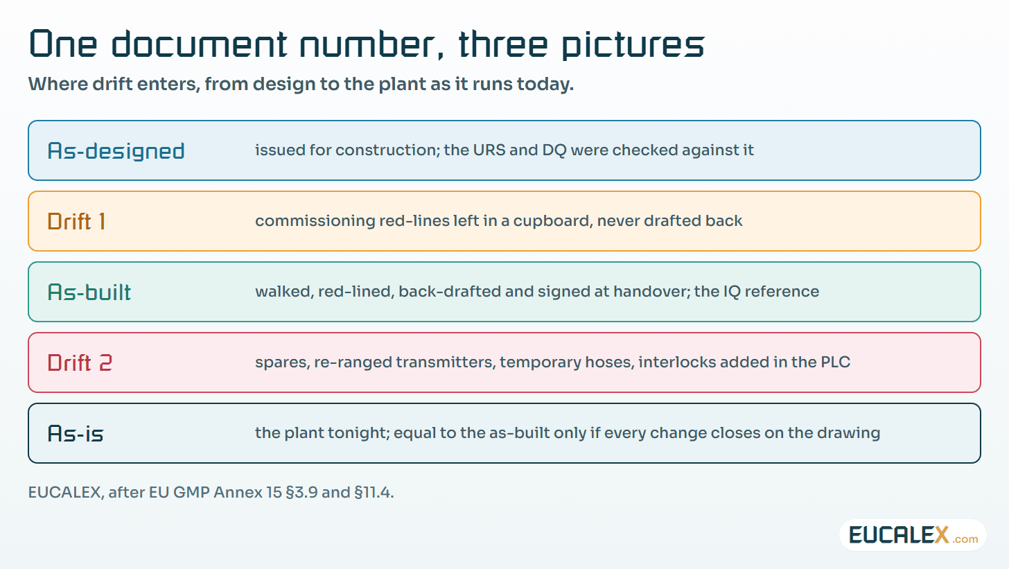
A qualified plant needs the last two to be the same picture. That is the whole subject of this article, and it is harder than it sounds.
What the drawings actually do on a GMP site
In a refinery the P&ID is first a safety document. In a pharmaceutical plant it is that, and also a piece of qualification evidence. EU GMP Annex 15, in operation since 1 October 2015, lists among the contents of an IQ the verification of the correct installation of components, instrumentation, equipment, pipe work and services against the engineering drawings and specifications (§3.9). When the IQ of a purified water loop or a CIP skid is signed, the engineering drawings at that revision become part of what was proven.
The P&ID shows dead legs, sample and drain points, product-contact valves and where clean steam reaches. The loop diagram shows how each instrument is wired, ranged and scaled to the controller input, and loop checks and calibration records mean something only if they point to the right one.
| Document | What it shows | Where qualification relies on it | What goes wrong when it drifts |
|---|---|---|---|
| Process flow diagram | Main equipment, streams, design flows and conditions | URS, process description, cleaning concept | Design basis no longer matches the plant; capacity changes go unassessed |
| P&ID | Every line, valve, instrument and interlock, with tags | DQ review, IQ walk-down, dead-leg and drainability checks, isolation planning | Wrong valve isolated; a sample point or bypass nobody qualified |
| Loop diagram or process loop sheet | Wiring to the terminal, ranges, signals, scaling | Loop checks, calibration, alarm limits | A recorded value that is wrong while looking plausible |
| Instrument index and control system tags | One line per tag: range, units, alarms, I/O address | Calibration programme, alarm list, data review | Tags in the system that exist on no drawing, and the reverse |
The standards behind the symbols
Symbols and tag letters mostly follow ANSI/ISA-5.1, whose current edition (October 2024) is titled Instrumentation and Control – Symbols and Identification and now includes a symbol table for loop instrument diagrams. Loop diagrams themselves are covered by ISA-5.4, still in its 1991 edition. European projects often add IEC 62424 (second edition, 2016), which defines how control requests appear on a P&ID and pass to the control engineering tool, and the DEXPI association works on a common exchange format for P&ID data. None of this keeps a drawing true on its own. A perfectly compliant symbol on the wrong line is still on the wrong line.
How a drawing drifts away from the field
Drift rarely comes from one big change. It comes from small ones, each perfectly reasonable on the day. The patterns repeat from site to site:
- Commissioning red-lines that never come home. The contractor marks up the paper set during start-up, the project closes, and the mark-ups sit in a cupboard instead of being drafted back. The “as-built” issued at handover is in fact the last design revision.
- Like-for-like that is not. A pressure transmitter is replaced by the current model from the same supplier. Same tag, different range. The technician re-ranges the controller input; the loop sheet still shows the old span.
- The temporary hose. Fitted during a shutdown to bypass a failed valve, left in place because it works. A year later it is part of the process and on no drawing.
- Logic nobody draws. A PLC change adds an interlock between two systems. The functional specification is updated, sometimes. The P&ID is not.
- Cables with no loop. A new Ethernet drop to a skid, a gateway for a vendor’s condition monitoring. The network drawing is the last document anyone thinks of.
The isolation error is the obvious cost, and a safety matter. The scaling mismatch is quieter and, in GMP terms, worse: if the transmitter measures 0 to 16 bar and the system still scales it as 0 to 10 bar, every value in the historian and the batch record is wrong, consistently, and nobody notices because the trend looks normal. That is a data integrity failure that no audit trail will show. The undocumented connection is a security matter: you cannot segment, monitor or patch what is not on any drawing, and the first complete inventory of a network is too often drawn by an incident responder.
What the rules ask, and what they leave to you
GMP texts never say “keep your P&IDs up to date” in those words. They get there by three routes. Annex 15 makes the drawings the reference of the IQ (§3.9), asks for equipment to be evaluated at an appropriate frequency to confirm it remains in a state of control (§4.1), and requires change control to assess impact on, among other things, documentation, validation, calibration and maintenance (§11.4). Chapter 4 of the EU GMP Guide asks for documents within the quality management system to be regularly reviewed and kept up to date (§4.5). Put together, a drawing used as qualification evidence is a controlled document, and a change that makes it untrue is not closed until the drawing is revised.
Annex 15 is being revised, but the EMA concept paper of January 2026 is aimed at active substance manufacturers and risk management, with a draft not planned before December 2026. No reason to wait for it.
US sites with a process covered by OSHA’s process safety management standard have a more explicit rule: 29 CFR 1910.119 lists piping and instrument diagrams in the required process safety information (§(d)(3)(i)(B)), and its management-of-change clause says that when a change alters that information, the information shall be updated accordingly (§(l)(4)). A solvent recovery unit on a pharmaceutical site can fall under both regimes. The PSM wording is worth borrowing even where it does not apply: it states plainly what GMP leaves implied.
Tying every revision to change control
The fix is not a better drawing tool. It is a few rules about who holds the pen and when a change may be closed.
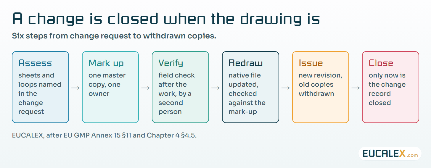
Three details make the difference in practice. The impact assessment names the sheets and loops it touches, and “none” is accepted only from someone who looked. Each system has one master mark-up and one owner, usually the process or system engineer, so two projects never red-line the same sheet two different ways. And the old copies are actually withdrawn: the laminated sheet in the panel door, the PDF on the shared drive, the printout in the maintenance office. If drafting takes three weeks, the change stays open for three weeks, in plain sight on the change control dashboard.
For changes to the control system, the loop sheet and the system configuration move together. If the controller input is re-ranged, the loop sheet, the instrument index and the calibration record change in the same record, and someone checks that the historian and batch reports read the new range. See also how to decide whether such a change needs requalification.
A legacy site whose drawings are wrong
Most sites do not start from clean drawings: some are right, some are wrong, and nobody knows which. Redrawing everything is rarely affordable. A walk-down campaign ordered by risk usually is.
| Priority | Systems | What to verify first |
|---|---|---|
| 1 | Product-contact and sterile systems: WFI and purified water, clean steam, CIP/SIP, sterile filtration, aseptic transfer | Dead legs, drain and sample points, valve tags, instrument ranges against loop sheets |
| 2 | Systems with safety functions: solvent handling, pressure vessels, inerting, exhaust and containment | Isolation points, relief devices, interlocks shown and wired as drawn |
| 3 | Systems whose data feed GMP records: environmental monitoring, temperature-controlled storage, weighing | Ranges and scaling from sensor to historian |
| 4 | Non-GMP utilities and buildings | Correct at the next modification, not before |
For each system, a two-person team walks the current P&ID and loop sheets, marks every difference and classifies it: a drawing error to correct, or a field condition nobody ever approved, which needs its own change request. The second category matters most. A hose that was never qualified is a deviation to assess, not a line to add to the drawing. Our article on how workarounds become normal covers that conversation.
Intelligent P&IDs, and where to keep them
Data-driven P&ID tools treat each valve and instrument as an object, so the instrument index, loop sheets and control system tags can in theory come from one database. The authors of the Automation.com feature note that these tools live mostly in engineering projects and seldom survive into plant maintenance, because of cost and the effort of keeping them consistent. That matches what we see: the model is handed over, nobody on site has the licence or the training, and two years later it is older than the PDF set. If a site wants it, the contract must ask for native files and a neutral export, and the site must name an owner. Otherwise a well-governed PDF set with a reliable revision history is worth more.
Where the drawings live matters too. A complete set of P&IDs, loop diagrams and network drawings is a map of the plant’s safety and control functions. On a cloud platform, treat it as sensitive: access by role, no anonymous share links, downloads recorded, and the GMP master in a validated document system rather than a collaboration folder.
Where to start
- Pick one critical system and walk its P&ID and loop sheets against the field with a process engineer and an instrument technician. The result tells you how big the problem is.
- Add a drawing line to the change request form, with the master mark-up owner as a required approver for any change that touches it.
- Make loop sheets part of instrument replacement. No transmitter swap is closed without the range on the loop sheet, the controller and the historian compared.
- Replace uncontrolled copies with controlled prints that carry the revision and issue date.
- Put a sample walk-down of a few sheets into the periodic review of each qualified system.
- Write the handover requirement into the next project: as-built drawings signed, native files, loop sheets for every tag, before the IQ of each qualification stage can be closed.
Five common mistakes
- Calling the last design revision “as-built”. If nobody walked it, it is as-designed with a new stamp.
- Drawing what you find without asking why. A field difference may be an unapproved change, and it deserves an assessment before it becomes a line on the P&ID.
- Updating the loop sheet but not the system. Or the reverse. The range has to agree from transmitter to historian.
- Leaving the network off the drawing set. Undocumented connections are the ones nobody protects.
- Treating drawings as an engineering matter only. On a GMP site they are controlled documents, and quality has to care when they are wrong.
A drawing is worth exactly as much as the last time someone checked it against the field. Make that check part of every change, and the night shift will find two valves where the P&ID shows two.
References
- European Commission, EudraLex Volume 4, Annex 15: Qualification and Validation, in operation since 1 October 2015, §3.9, §4.1, §11.4.
- European Commission, EudraLex Volume 4, Chapter 4: Documentation, in operation since 30 June 2011, §4.5.
- EMA GMP/GDP Inspectors Working Group, Concept paper on the revision of Annex 15, EMA/INS/GMP/163466/2026, 19 January 2026.
- ISA, ISA-5 series: ANSI/ISA-5.1-2024, ISA-5.4-1991 and technical reports.
- IEC, IEC 62424:2016, Representation of process control engineering – Requests in P&I diagrams and data exchange between P&ID tools and PCE-CAE tools.
- OSHA, 29 CFR 1910.119, Process safety management of highly hazardous chemicals, §(d)(3)(i)(B) and §(l)(4).
- A. Éthier and M. Roy, “The Importance of Maintaining P&ID Accuracy”, Automation.com magazine, August/September 2025 (a starting point of this article).
- J. R. Davis and G. Nasby, “Understanding Loop Diagrams & Process Loop Sheets”, InTech, October 2023 (a starting point of this article). isa.org
Related articles
All articles- When does a repair become a requalification? Change control on qualified equipmentA qualification report describes a machine on the day it was signed. Every repair, spare part and program edit after that day either keeps the…
- When the workaround becomes normal: drift, “operator error” and CAPAs that change nothing on a GMP siteNobody decides to accept a bypassed interlock or a deviation that keeps coming back; teams drift there one reasonable step at a time. How it shows…
- DQ, IQ, OQ, PQ: what each qualification stage proves, and what it cannotFrom the quality concept and the URS to the PQ, one question per stage. A plain reference for the engineers and technicians who sign qualification…
EUCALEX
Have a project or a technical challenge?
Contact us: we will be pleased to discuss it with you, with no commitment.
Discuss your project with usStay informed
Receive new EUCALEX articles and technical insights by email.