
When a transmitter checks itself, what does the calibration record actually prove?
The metrology technician pulls the temperature probe from the bioreactor jacket line during the annual shutdown, puts it in a dry block next to the reference and writes the as-found reading. At 121 °C the loop, read on the control system screen, sits 0.8 °C above the reference. The calibration tolerance on the tag sheet is ±0.5 °C. Quality wants to know which batches are affected. The process engineer opens the transmitter’s diagnostic history: a self-check after every sterilisation cycle, all passed.
Both records are true. The self-check compared the sensing element with an internal reference at one temperature. The error sat elsewhere, in a range change made months earlier with a handheld tool during a troubleshooting call, which nobody wrote down. The device was healthy. The measurement was wrong.
That scene is a composite, but each part of it turns up on the sites we assess. Its lesson is the thesis of this article: a self-check, a verification and a calibration answer three different questions, and a good manufacturing practice (GMP) calibration record is worth what it says about which one was done, on which part of the loop, against which tolerance, and by whom.
What the texts actually require
The GMP texts are short on calibration, and they say more than people remember.
| Text | What it says | What it leaves to the site |
|---|---|---|
| EU GMP Part I, Chapter 3, §3.41 | Measuring, weighing, recording and control equipment “should be calibrated and checked at defined intervals by appropriate methods”, with adequate records | The interval, the method and what counts as a check |
| EU GMP Annex 15 (2015), §3.9 (iv), §5.22 (vi), §11.4 | Calibration of instrumentation is part of installation qualification (IQ); a process validation protocol lists the equipment with its calibration status; every change is assessed for its impact on calibration | Which instruments matter to the validated state |
| 21 CFR 211.68(a) | Automatic and electronic equipment is “routinely calibrated, inspected, or checked according to a written program designed to assure proper performance”, with written records | Which of the three verbs applies to which device |
| 21 CFR 211.160(b)(4) | A written programme with “specific directions, schedules, limits for accuracy and precision, and provisions for remedial action”; equipment out of specification shall not be used | Strictly a laboratory control, used by most sites as the template for all instruments |
| ISA-RP105.00.01-2017 (International Society of Automation recommended practice) | A framework for a calibration programme for automation and control systems, built on the loop rather than the field instrument alone | A recommendation, not a regulation |
Section 211.68(a) already accepts that some equipment is “checked” rather than calibrated, so a diagnostic routine has a place, provided the written programme says what it covers. None of these texts sets an interval: the yearly round most plants use is a habit. And the ISA practice sets the tolerance on what each loop must achieve, not on the rated accuracy of the device. Why calibration is checked at installation at all is set out in our reference on what each qualification stage proves.
Four words the metrologists keep apart
The International Vocabulary of Metrology (VIM), published by the Joint Committee for Guides in Metrology (JCGM) as JCGM 200:2012, settled these words before smart transmitters spread, and it is sharper than most procedures.
- Calibration (VIM 2.39). An operation that relates the values of a measurement standard, with their uncertainties, to the indications of the instrument, then uses that relation to obtain results. Note 2 of the entry is worth quoting in full: “Calibration should not be confused with adjustment of a measuring system, often mistakenly called “self-calibration”, nor with verification of calibration.”
- Verification (VIM 2.44). The provision of objective evidence that an item fulfils specified requirements, for instance that a manufacturer’s specifications are met. A pass or a fail, not a correction.
- Adjustment (VIM 3.11). The set of operations that makes the instrument give prescribed indications: zero, offset, span. Calibration comes first; adjustment, if any, follows.
- Maximum permissible error (VIM 4.26). The extreme error a specification or regulation permits. On a GMP site it is the tolerance on the calibration sheet, and it must come from somewhere.
A device diagnostic fits none of these exactly. It is a monitoring signal: the device telling you about its own state, against criteria its maker chose. It can be very useful evidence. It becomes calibration evidence only for the part of the measurement it actually compares with a reference.
| Activity | What is compared | What it proves | What it does not prove | What the record must hold |
|---|---|---|---|---|
| Device self-check | Internal state against its maker’s criteria | No fault it was designed to detect | That the reading on the control system is right | Status, time, diagnostic configuration |
| In-situ verification | One or more points against a reference, no adjustment | In tolerance at those points | Behaviour between the points | As-found values, reference, pass or fail |
| Calibration | Several points across the range against a traceable standard | The error and its uncertainty over the range used | That nothing changes after the visit | As-found, as-left, standard, tolerance, who and when |
| Adjustment | Nothing; it changes the instrument | Nothing by itself | Anything about the past | Done only after the as-found is recorded |
Rank the instruments before setting a single interval
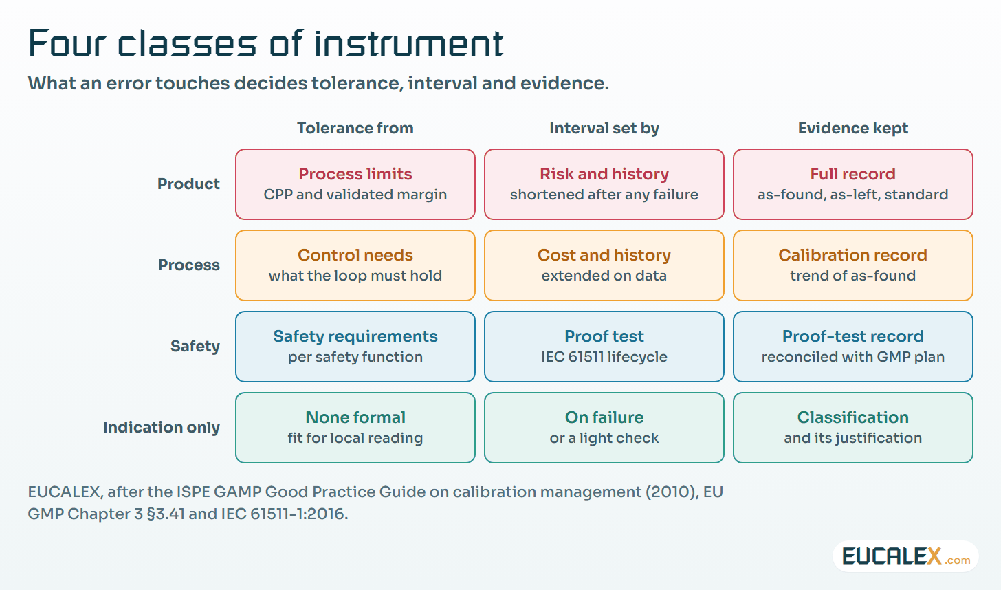
A sound programme starts with unglamorous work: a list of every instrument, and for each a judgement on what its error would touch. The ISPE GAMP (Good Automated Manufacturing Practice) guide on calibration management, Second Edition of November 2010, puts this criticality assessment before anything about intervals.
The split we use on site has four classes: product, process, safety, and local indication only. They are not exclusive. A sterilisation temperature can be product-critical and safety-relevant at once, and then the stricter rule of each applies. A safety instrument inside a safety instrumented function takes its test interval from the safety requirements under IEC 61511-1 (edition 2.0, 2016), and the two plans are reconciled tag by tag. The reasoning is the one that sets test depth by risk in a qualification: effort follows what a failure would cost.
Tolerance comes from the process, not the datasheet
The most common weakness we find in calibration records is a tolerance copied from the transmitter datasheet. The datasheet says what the device can do. The process says what it must do. They are different numbers, and only the second one belongs on a GMP calibration sheet.
Take an illustrative case. A sterilisation hold needs 121 °C or above and the cycle runs at a 122 °C set point. If the measurement can be 1 °C wrong unnoticed, the margin is gone. So the process tolerance comes from that margin, the calibration tolerance sits inside it, and the field reference’s uncertainty is small against both. The three numbers are written down together, with the reasoning.
That layering is what makes an out-of-tolerance result manageable. A loop found beyond the calibration tolerance but inside the process tolerance is a maintenance event and a signal about the interval. A loop beyond the process tolerance is a quality event. Without the two lines, every finding is argued from scratch while batches wait.
When the as-found reading fails
Section 211.160(b)(4) asks for “provisions for remedial action” in the written programme, and for equipment out of specification to be taken out of use. On a production line, the remedial action that matters is the look backwards: which batches did this loop measure since it was last known to be good?
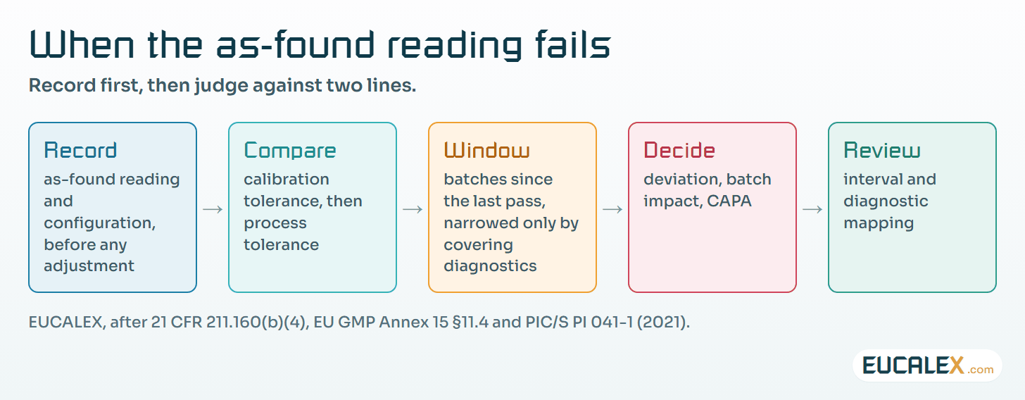
The as-found value is the single most important figure in the record, and the easiest to lose. A technician who adjusts first and writes afterwards has destroyed the evidence the impact assessment needs. PIC/S PI 041-1 (1 July 2021) describes the original record as the first capture of information, and lists calibration among the equipment factors that make a record accurate. Applied here, the as-found is the original, written at the time, by the person who read it.
The window under assessment runs back to the last calibration that passed. This is where device diagnostics earn their place. If the self-check covers the drift mode found, and its history shows when it started, the window can shrink from a year of batches to a few weeks. If it does not cover that part of the loop, as in the opening scene, it shrinks nothing, and saying otherwise in a deviation report will not survive an inspector’s second question.
What a self-checking sensor really does
The best known example is a hygienic resistance thermometer with a built-in reference whose Curie point, the temperature at which a material’s ferromagnetic behaviour changes abruptly, sits at 118 °C. Each time a steam sterilisation cycle cools through that point, the device compares its own reading with the reference. Its maker states, in its launch announcement of 16 November 2017, that this comparison “is a calibration”, that a deviation outside set limits raises an alarm, and that up to 350 results are stored.
Read against the VIM, the claim holds for what it covers: a comparison with a reference at one point, on the sensing element, in place. It is a one-point calibration of the sensor. It says nothing about the rest of the range, about the transmitter output, about the input card or about the scaling in the controller. For a sterilisation loop whose critical value sits close to 118 °C, that is a strong piece of evidence. For a fermentation loop controlled at 37 °C, much less.
Built-in flowmeter verification raises the same question. The calibration plan feature published in InTech in July/August 2019 says such methods, when traceable, can supplement a calibration plan. Supplement is the right word.
Diagnostics and the four status signals
Most smart instruments now report their condition under the four status signals of NAMUR recommendation NE 107, “Self-Monitoring and Diagnosis of Field Devices”, revised in an edition dated 10 April 2017: failure, function check, out of specification and maintenance required. One of the 2022 magazine items behind this article calls it “NE017”; the recommendation is NE 107.
What matters for GMP is that the mapping is configurable: the fieldbus and HART (Highway Addressable Remote Transducer) implementations let the user decide which diagnostic lands in which signal. A drift alarm can become “maintenance required”, “out of specification”, or nothing. That setting decides whether anyone sees the drift, so it belongs to the validated configuration and goes under change control like a set point.
Extending an interval on the strength of diagnostics
Diagnostics are a fair argument for a longer interval, under conditions that we would write into the procedure rather than argue case by case:
- A history first. Several consecutive as-found results inside the calibration tolerance, on this tag or on a documented family of identical tags in the same service.
- Coverage of the dominant drift. The diagnostic must watch the failure mode that the as-found history shows. Element drift, yes; a moved range or a corroded terminal, usually not.
- A risk assessment and a change record. Annex 15 §11.4 lists calibration among the things a change must be assessed against. An interval is part of the validated state.
- A way back. One failed as-found returns the tag to the shorter interval until the history is rebuilt.
For product-critical loops we would extend one step at a time, never skip calibration altogether, and keep the multi-point check that covers what the self-check cannot see.
Who may change the range from a phone
Many transmitters can now be configured from a handheld, a laptop or a phone app over Bluetooth, without opening the housing. Range, units, damping, sensor trim: each of these changes the number the batch record will carry. A damping value raised to calm a noisy trend can hide the very excursion an alarm was meant to catch.
The principle is written down. Annex 11 §10 wants changes to a computerised system, “including system configurations”, made in a controlled manner under a defined procedure, and §12.1 restricts access to authorised persons. PIC/S PI 041-1 §9.5 expects critical operating parameters to be protected and changed through change management; §9.6 accepts that very simple systems lack an audit trail, provided other controls verify the data.
A field transmitter is usually one of those simple systems. Few record who changed a parameter, and a log kept in the handheld or the app stays with the tool, not with the plant. So the record has to be built around the device:
- write protection enabled on product-critical tags, by switch or by password, and Bluetooth off or paired only with managed tools;
- a configuration snapshot taken at installation and compared at each calibration, the as-found configuration recorded alongside the as-found reading;
- every configuration change made under a work order that names the person, the tag, the old and new values, and the reason;
- these features required in a user requirements specification that drives the qualification, which is cheaper than discovering their absence at installation qualification.
Where to start
- Pick the ten product-critical loops of one line and, for each, write the process tolerance, the calibration tolerance and where each number comes from. If a tolerance came from a datasheet, you have found your first correction.
- For the same ten loops, record which part of the loop each device diagnostic covers, and how its NE 107 mapping is set. This takes a morning with the instrument technician and the configuration tool.
- Check the last calibration record of each: is the as-found written before the adjustment, and is the configuration recorded too? The answer tells you what the next out-of-tolerance investigation will be able to prove.
Five common mistakes
- Adjusting before recording. The as-found is the evidence for every batch since the last calibration. Once overwritten, the impact assessment rests on assumptions.
- The datasheet tolerance. A transmitter accuracy is not a process requirement. Tolerances on GMP calibration sheets come from the process.
- Calling a self-check a calibration without saying which part of the loop it covers. The inspector will ask, and the answer has to be in the record, not in the vendor brochure.
- Calibrating the transmitter and forgetting the loop. Input card, scaling and display are part of the measurement the batch record uses.
- Leaving configuration access open. A range changed over Bluetooth to solve a night-shift problem is a change to a validated system with no record.
A diagnostic tells you the device is well. Only a comparison with a reference, across the range the process uses, tells you the number on the batch record is right.
References
- European Commission, EudraLex Volume 4, EU GMP Part I, Chapter 3: Premises and Equipment, in operation since 1 March 2015, §3.40 and §3.41.
- European Commission, EudraLex Volume 4, Annex 15: Qualification and Validation, in operation since 1 October 2015, §3.9, §5.22 and §11.4.
- European Commission, EudraLex Volume 4, Annex 11: Computerised Systems, revision of January 2011, §10 and §12.1.
- US FDA, 21 CFR Part 211, Current Good Manufacturing Practice for Finished Pharmaceuticals, sections 211.68(a) and 211.160(b)(4).
- PIC/S, PI 041-1, Good Practices for Data Management and Integrity in Regulated GMP/GDP Environments, 1 July 2021.
- JCGM, JCGM 200:2012, International Vocabulary of Metrology (VIM), 3rd edition, entries 2.39, 2.44, 3.11 and 4.26.
- ISA, ISA-RP105.00.01-2017, Management of a Calibration Program for Industrial Automation and Control Systems.
- ISPE, GAMP Good Practice Guide: A Risk-Based Approach to Calibration Management, Second Edition, November 2010.
- Setting up an instrument calibration plan, Automation Basics, InTech, July/August 2019, pp. 38-39.
- Temperature Instruments Improve Operations, InTech FOCUS Temperature & Pressure, May 2022 (online June 2022).
Related articles
All articles- How deep should a qualification test go? Tie test depth to risk, then prove coverage with a traceability matrixTest scripts multiply until nobody can say what they prove. Three rules bring them back under control: qualify only the functions you use, set the…
- DQ, IQ, OQ, PQ: what each qualification stage proves, and what it cannotFrom the quality concept and the URS to the PQ, one question per stage. A plain reference for the engineers and technicians who sign qualification…
- Ethernet down to the transmitter: what Ethernet-APL changes for instruments, networks and GMP change controlEthernet-APL puts a 10 Mbit/s Ethernet link and its power on one twisted pair, out to the transmitter in Zone 0. The data is real. So are the two…
EUCALEX
Have a project or a technical challenge?
Contact us: we will be pleased to discuss it with you, with no commitment.
Discuss your project with usStay informed
Receive new EUCALEX articles and technical insights by email.