
Ethernet down to the transmitter: what Ethernet-APL changes for instruments, networks and GMP change control
The loop check on a new skid used to be a two-person job with a known rhythm. One technician at the marshalling cabinet, one at the transmitter, a calibrator injecting 4, 12 and 20 mA, and the operator in the control room reading back 0, 50 and 100 % of range. Tick, sign, next tag. On the first skid built with Ethernet-APL instruments, the rhythm breaks in a place nobody planned for. The transmitter answers before anyone has touched it. It has an address, a name, a web of parameters, a firmware version and a diagnostic status. Then the network engineer walks over and asks the question that ends the morning: who owns this device, and which zone is it in?
That question is the real subject of Ethernet-APL. The physics is solved. What a plant still has to decide is how an instrument that is now a networked computer gets engineered, secured, maintained and, on a GMP site, kept under change control.
What the analogue loop never had to answer
Most process plants still measure with two wires and a current: the transmitter draws 4 to 20 mA, the current is the value, and that is all the control system sees. HART added a digital conversation on the same pair, at 1.2 kbit/s according to the APL project’s own comparison. Enough to change a range with a handheld, never enough to stream diagnostics from a plant.
Fieldbus (PROFIBUS PA, FOUNDATION Fieldbus H1) went further, at 31.25 kbit/s on a shared trunk, and left the cabling and junction boxes that Ethernet-APL now reuses. It never became the default: one of the technology’s promoters put it at about a fifth of the industry in a 2022 interview, an estimate rather than a census. Meanwhile the instruments became small computers whose diagnostics and settings rarely leave the housing. The bottleneck was never the sensor. It was the wire.
What Ethernet-APL actually is
Ethernet-APL is a physical layer, nothing more. It takes 10BASE-T1L, the single-pair Ethernet of IEEE Std 802.3cg-2019 (an amendment since superseded and carried into IEEE 802.3), and adds what a process plant needs: long reach, power on the same pair, and protection for hazardous areas.
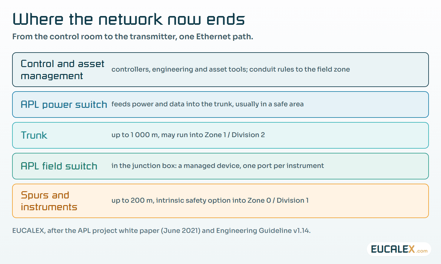
In the APL project’s figures, a link runs at 10 Mbit/s, full duplex. The topology borrows from fieldbus: a powered trunk of up to 1 000 m that may run into Zone 1, field switches in the junction boxes, and spurs of up to 200 m to each instrument, with an intrinsic safety option into Zone 0. In North American practice, Zones 0 and 1 both sit inside Class I Division 1, and Zone 2 corresponds to Division 2. Unlike fieldbus, every connection is point to point: each segment links exactly two partners through a switch, so a faulty device cannot drag its neighbours down. The reference cable is the fieldbus type A cable of IEC 61158-2, which is why a brownfield site with PROFIBUS PA or H1 already in the trays starts with an advantage.
Intrinsic safety rests on 2-WISE, the 2-Wire Intrinsically Safe Ethernet concept of IEC TS 60079-47, which sets fixed intrinsic safety limits for APL ports so that a segment is verified by a short set of rules rather than by calculation. It is still edition 1.0 of February 2021, and still a Technical Specification, not an International Standard. Check what your notified body and your installation rules accept, and do not write “IEC 60079-47” in a specification as if the full standard existed.
Above the physical layer travel ordinary Ethernet frames, so the protocol is a choice: the APL white paper names EtherNet/IP, HART-IP, OPC UA and PROFINET. FieldComm Group, ODVA, the OPC Foundation and PROFIBUS & PROFINET International launched the technology on 15 June 2021, at the ACHEMA Pulse virtual event.
| Aspect | 4–20 mA with HART | Fieldbus (PA, H1) | Ethernet-APL |
|---|---|---|---|
| Signal | One analogue value, HART at 1.2 kbit/s | Digital, 31.25 kbit/s, shared bus | Ethernet, 10 Mbit/s full duplex |
| Topology | One pair per instrument, to the marshalling cabinet | Trunk and spurs on a bus | Trunk and spurs, switched, point to point |
| Who can talk to the device | The controller; a handheld on the loop | The host, often through gateways | Any authorised client on the network, in parallel |
| What it adds to maintenance | A known, simple loop check | Segment diagnostics, bus tools | Switches, addresses, firmware, network monitoring |
The data it frees, and the model that makes it readable
A flat Ethernet path to the instrument is only useful if every vendor’s transmitter describes itself the same way. That is the job of PA-DIM, the Process Automation Device Information Model published as OPC 30081. It is built on NAMUR’s recommendations for the NAMUR Open Architecture (NE 175), for self-monitoring and diagnosis of field devices (NE 107) and for standard devices (NE 131), and ties parameters to IEC 61987 dictionary identifiers, so that a pressure from one vendor means the same thing to the historian as a pressure from another. It has moved on since 2022: version 1.02 is current, with process analysers added along the way.
The gain is concrete. Instrument health reaches maintenance without a walk to the field. Asset management reads the device in parallel with the controller, one of the points the APL project stresses most. On a pharmaceutical site the same path can carry calibration status and diagnostic history that a metrology team still collects by hand.
Read the same model with the other eye and it lists what can be done to the device from the network. Among its methods, PA-DIM defines a zero-point adjustment and a factory reset. Both are legitimate. Both are also changes to a measuring instrument, made remotely.
Site reality: brownfield, cable and people
The promise of reusing installed fieldbus cable is real, with a condition the APL Engineering Guideline states plainly: an existing cable must be measured before it carries APL. Version 1.14 of the guideline, the one the APL project still publishes, asks for an examination following ISO/IEC 11801-3 and sorts cables into four categories. A cable that only meets category I is good for a 250 m trunk, not the 1 000 m of the brochure. Old cables with poor shielding are the usual casualties. Budget the measurement campaign before the migration, not after the first intermittent link. The guideline also gives a chapter to spare ports and power reserves on the trunk: plan both, because the extension that arrives three years later always needs one more port in the junction box that is already full.
Then come the people, and this is where projects slip. Instrument technicians know loops, barriers and calibrators. Network engineers know VLANs and addresses, and rarely set foot in a Zone 1 area. Ethernet-APL needs both skills at the same junction box, under the same permit, with a cable tester next to the screwdriver. The loop check does not disappear; it changes shape. The acceptance test of the installation (visual inspection, cable measurement) comes first, then the device’s identity and configuration are checked against the engineering database, then the value against a reference. On a validated line, each step needs a test script and a record. The first APL skid on a site usually takes longer to commission than the analogue one it replaces. The second one does not.
Every transmitter becomes a network node
The APL white paper states, correctly, that as a physical layer only, Ethernet-APL carries whatever safety and security services the protocols above it provide, citing IEC 61508 and ISA/IEC 62443. Read on site, that sentence means the security is your job, not the cable’s.
An APL instrument has an address, a firmware image and open services, sometimes a web server or an OPC UA endpoint. It belongs in the asset inventory with the same fields as a PLC. The field switches are network devices with management interfaces and firmware of their own. The instruments and switches of one process unit form a zone, and the link back to the controllers is a conduit with rules on it, as described in zones and conduits. The network the brochures call flat is flat for engineering convenience; it should not be flat for an intruder.
When you buy, IEC 62443-4-2 (still its first edition, 2019) gives the vocabulary for what a component must be able to do, from identification and authentication to use control and integrity. The Cyber Resilience Act adds the legal side for the manufacturer: its reporting obligations have applied since 11 September 2026, and its essential requirements apply from 11 December 2027, which is why the questions in CRA Annex I for buyers belong in an instrument tender as much as in a machine one.
Patching is the hard part. A firmware update on a transmitter in a qualified loop is a change to a measuring device, not an IT chore. Agree with the vendor how often firmware is issued, how it is signed, what it changes in the measurement, and how the device proves which version it runs.
Every writable parameter becomes GMP configuration
With 4–20 mA, the range, damping and units of a transmitter were changed by someone standing in front of it with a handheld. Physical presence was the control, imperfect but real. With Ethernet-APL, anyone with a route and the right tool can change them from a desk two buildings away.
EU GMP has not changed for this; it simply applies further down. Chapter 3 asks that measuring and control equipment be calibrated and checked at defined intervals, with records. Annex 11, still the January 2011 text in force today (its revision went to consultation from 7 July to 7 October 2025), asks in clause 10 that “any changes to a computerised system including system configurations should only be made in a controlled manner in accordance with a defined procedure”, and in clause 12.1 that access be restricted to authorised persons. A networked transmitter’s range or damping is exactly such a configuration. If it can be changed remotely, three questions need an answer before the first batch.
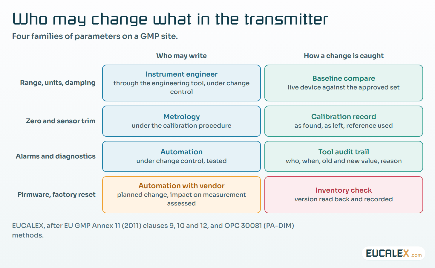
- Who may write. Most clients only need to read. Route the write path through one engineering or asset management tool with named accounts, and set the device’s own write protection where it offers one.
- How a change is seen. Keep an approved configuration baseline per tag and compare the live device against it on a schedule and after every intervention. A damping value moved from 2 to 8 seconds raises no alarm; it quietly smooths the excursion QA needed to see.
- How it is recorded. A change through the tool should leave who, when, old value, new value and reason, the audit trail Annex 11 clause 9 describes. A change made around the tool is caught by the comparison above and handled as a deviation.
None of this needs new technology, only people from instrumentation, networks and QA writing the same procedure. Whether a remote parameter change on a qualified loop is a simple change or a requalification is treated in when a repair becomes a requalification; the answer does not depend on the cable.
Where to start
- Pilot outside the batch record. A utility or a non-GMP area (cooling water, a tank farm) teaches the installation, the tools and the failure modes without a validation dossier on every mistake.
- Measure before you reuse. Survey the installed fieldbus cable against the guideline’s categories and keep the result per segment. It is the first thing asked for when a link drops.
- Put instruments in the inventory now. Tag, model, firmware, address, switch port, zone, owner. An inventory started on day one stays true; one rebuilt in year three never does.
- Write the URS lines and the procedure. Protocol, PA-DIM support, IEC 62443-4-2 capabilities, write protection, audit trail of configuration changes, firmware signing and support period, 2-WISE certification; then parameter families, roles and baseline comparison in a GMP procedure before go-live.
Five common mistakes
- Treating APL as a cabling project. The electricians finish, the instruments answer, and nobody has decided addressing, zones or who owns the switches.
- Reusing cable on faith. Fieldbus type A in the tray is a good start, not a test result.
- One flat network from the field to the office. Convenient for the asset management tool, and just as convenient for anything else that gets onto it.
- Leaving every client with write access. Reading health data from everywhere is the point; writing ranges from everywhere is a data integrity finding waiting to happen.
- Forgetting the old skills. Analogue loops and fieldbus will run beside APL for decades, and so must the people who know them.
Ethernet-APL gives the field its network. Decide who owns it, who may write to it and how a change is seen before the first transmitter answers, and the data it frees becomes evidence rather than exposure.
References
- OPC Foundation, The Industrial Interoperability Standard, OPC eBook #06, August 2022, chapter 4 “OPC UA and Ethernet-APL” (interview by Michael Clark) and chapter 3 “OPC UA and the PA-DIM specification”: opcfoundation.org
- APL project, Ethernet – To the Field, white paper, June 2021: ethernet-apl.org
- APL project, Ethernet-APL Engineering Guideline, version 1.14, September 2022: ethernet-apl.org
- IEEE Std 802.3cg-2019, 10 Mb/s operation over a single balanced pair of conductors: standards.ieee.org
- IEC TS 60079-47:2021, Explosive atmospheres – Part 47: Equipment protection by 2-wire intrinsically safe ethernet concept (2-WISE): webstore.iec.ch
- OPC 30081, Process Automation Devices – PADIM: opcfoundation.org
- IEC 62443-4-2:2019, technical security requirements for IACS components: webstore.iec.ch
- EudraLex Volume 4, Annex 11: Computerised Systems (2011): health.ec.europa.eu
Related articles
All articles- Siemens networks from PPI to PROFINET: what each one is, where it still runs, and how to keep it workingAn older plant often runs four Siemens networks at once: a PPI or MPI programming link, PROFIBUS to drives and remote I/O, a Modbus device behind a…
- Solvent rooms and powder suites: explosive atmospheres on a pharmaceutical site, and what they ask of automationEthanol in the granulation suite, powder in the mill, a panel PC on the wall. What the two ATEX directives split between supplier and site, how to…
- Which measurements can go wireless? WirelessHART, ISA100 and the gateway you must secureWireless transmitters are mature. The real decision is which readings may depend on a radio, and how the gateway, the join keys and the GMP record…
EUCALEX
Have a project or a technical challenge?
Contact us: we will be pleased to discuss it with you, with no commitment.
Discuss your project with usStay informed
Receive new EUCALEX articles and technical insights by email.