
Recording what a running PLC does: signal analysers, what they see, and what they change on a validated line
The filling line stops twice a week, always in the middle of a batch, always for less than a second. The HMI shows a generic “infeed not ready” and nothing else. The alarm log has the stop but not its cause. Maintenance has swapped a sensor, then a cable, then a valve, and the line still stops. In the third week somebody turns up with a laptop, plugs it into the controller’s programming port, ticks forty signals in a PC tool and leaves it recording over the weekend. On Monday the answer is on the screen: one limit switch drops out for 120 ms while the star wheel indexes.
That is what a PLC signal analyser is for, and it is very good at it. It is also the moment a quality engineer should ask the three questions nobody asked on the Friday. Did the tool change anything in the controller? Who else can now reach that laptop? And is the recording going to end up in a deviation report as evidence?
What a PLC signal analyser is
A signal analyser is software on a PC that reads the memory of a running controller (inputs, outputs, flags, timers, counters, data words) through the channel the engineering software already uses: the programming port, the fieldbus or the plant Ethernet. It draws the values as traces on a time axis, a bit like an oscilloscope for the PLC program, and adds things an oscilloscope cannot do. It can trigger on logical conditions (“store ten seconds before and after the moment input A and output B are both true”), compare two recordings, measure the time between edges and run long unattended recordings.
The appeal is easy to see. There is nothing to wire, the tool reuses the symbols of the PLC project, and a technician can watch the program’s behaviour without being a programmer. The vendor documentation we reviewed sells exactly that: the tool “usually requires no software or hardware modifications to the PLC”. Keep an eye on the word usually; we come back to it below.
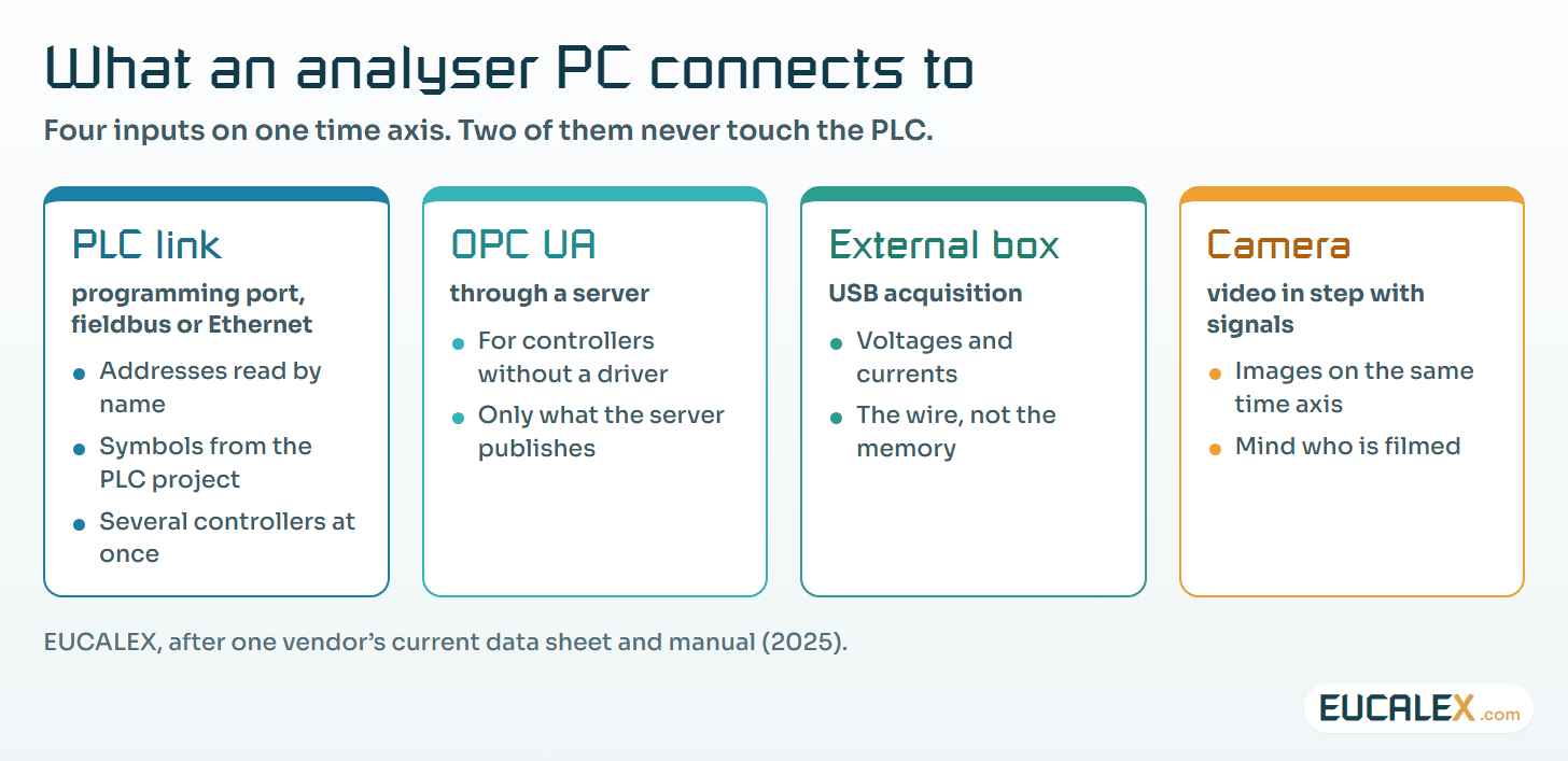
Current tools also bring other inputs onto the same time axis: an OPC UA server, for controllers without a dedicated driver; a small USB acquisition box for external voltages and currents; and a camera whose images are recorded in step with the PLC signals, so that the trace and the machine’s movement can be read side by side.
Four ways to watch a running controller
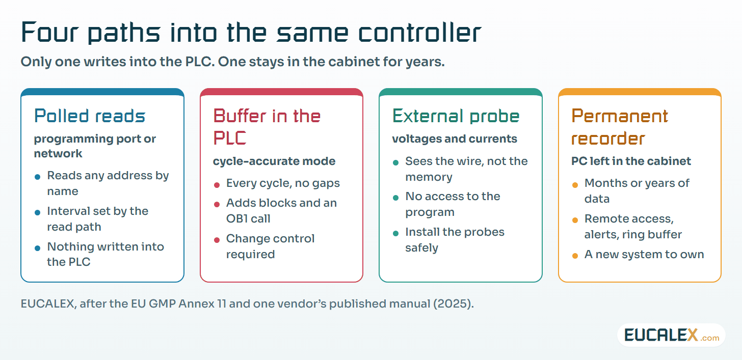
Behind the same screen sit four quite different techniques. They do not see the same things and do not cost the same, and only one of them leaves the controller exactly as it was.
| Technique | What it sees | Time resolution | What it changes |
|---|---|---|---|
| Polled reads over the programming or network interface | Any PLC address, by name | Limited by the read interval, not by the PLC cycle | Nothing in the program; adds load on the CPU and the network |
| Buffer inside the PLC (“cycle-accurate” mode) | Every PLC cycle, without gaps | One PLC cycle | Adds blocks and a call to the program: a change |
| External measurement of voltages and currents | The wire, not the memory | Set by the acquisition hardware | Nothing in the PLC; the probes must be installed safely |
| Permanent recorder left in the cabinet | Whatever it was configured to poll, for years | As for polled reads | A new computerised system on the control network |
1. Polled reads: the interval decides what you can see
In the usual mode the PC asks the controller for the selected addresses, receives the answer, and asks again. The controller does not wait for the PC. It keeps running its cycle, and the PC gets a snapshot whenever its request is served. That has two consequences.
Short events can fall between two reads. If a signal is true for 20 ms and the PC reads every 40 ms, the event may show up, or it may not, and a recording without the glitch proves nothing about the glitch.
The interval also grows with what you ask for. As an order of magnitude measured on site, expect about 25 to 30 ms per scan for one byte on an S7-300 read over MPI or PROFIBUS, plus about 2 ms for each additional byte; on an S7-1500 over PROFINET the practical floor is at least 1 ms for an S7-1500 read over PROFINET. Forty signals on an old controller are not forty signals on a new one.
So before trusting a recording, compare the read interval with the duration of the event you are chasing and with the PLC cycle time. If the interval is not clearly shorter than the event, record fewer signals, use a faster path or change technique.
| Event you are chasing | Read interval shorter than the event | Read interval longer than the event |
|---|---|---|
| A state that lasts seconds (a door open, a valve stuck) | Seen reliably | Seen, timing approximate |
| A glitch of a few PLC cycles | Seen if the interval is well below it | May be missed: absence proves nothing |
| A single-cycle pulse | Rarely guaranteed | Not visible: use a buffer or an external probe |
2. The “cycle-accurate” mode writes into the PLC
To see every cycle, some tools stop asking from outside and store the values inside the controller. The vendor manual we reviewed is explicit about how. The software looks for free block numbers, creates one function block and two data blocks, and adds a call to the new function block at the end of OB1. It may switch the controller to STOP to load these blocks, and again to remove them. Its own warning reads: “an influence of this modification on the mode of operation of the PLC or the PLC program cannot be completely excluded.”
On a validated line that is a modification of the application software, however temporary, and EU GMP Annex 11 §10 is brief on the subject:
“Any changes to a computerised system including system configurations should only be made in a controlled manner in accordance with a defined procedure.” (EU GMP Annex 11, §10)
The cycle-accurate mode therefore goes through change control like any other program change: impact assessment, approval, the equipment in a safe state while the blocks are loaded and removed, a check afterwards that the original program is back (compare the online blocks with the approved version), and a record. Our note on change control and requalification covers how to size the retest. The polled mode writes nothing and should be the default; the buffer is the exception you justify.
3. A recorder in the cabinet is a new system on the network
The same tools also come as a small industrial PC installed in the control cabinet, recording around the clock for months or years. The vendor documentation we were given lists what makes it convenient: remote operation over the plant LAN or over the internet through a VPN, e-mail and SMS alerts when a trigger fires, and automatic deletion of the oldest recording when the disk is full. Every one of those features is a question for the OT security and quality teams.
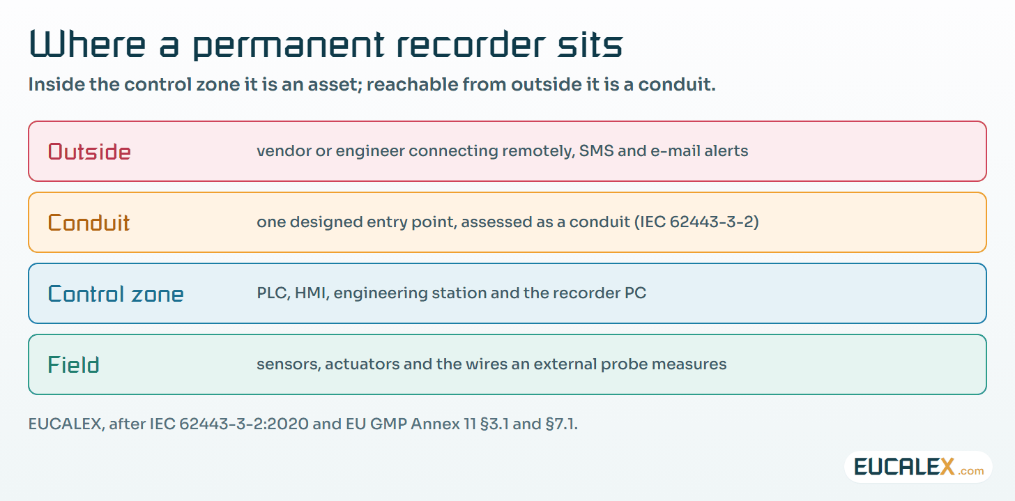
- Remote operation is remote access into the control zone. Annex 11 §3.1 expects formal agreements with third parties who maintain a system “e.g. via remote access”. On the network side, IEC 62443-3-2 asks for the system to be partitioned into zones and conduits, with the risk assessed for each. A recorder reachable from outside is a conduit and has to be designed as one; see vendor remote access without opening your cell network and zones and conduits.
- Alerts leave the plant. An SMS or e-mail gateway on a control-network PC is an outbound path most firewall rules never planned for.
- The oldest data disappears by design. Annex 11 §7.1 asks that access to data be “ensured throughout the retention period”. A ring buffer is fine for diagnostics. It is not a retention strategy for anything you may need to show an inspector.
- The links keep getting wider. The current version of one such recorder is sold with 4G/5G modem, WAN and LAN options for remote service, and a mobile modem in a control cabinet goes straight round every firewall on the site.
The last point is the least glamorous: it is a Windows PC in a cabinet. It needs patching, anti-malware suited to OT, backups and an owner, exactly like the engineering station it resembles.
4. What a recording is worth in an investigation
The 2010 manual we were given presents recordings as irrefutable evidence when looking for the cause of an incident. To an engineer, a clean trace is indeed convincing. A GMP deviation asks something else: can the data be trusted as a record? Four points decide it.
- Time. The time stamps usually come from the PC clock, not the controller. If the PC is not synchronised with the site time source, the trace cannot be lined up with the batch record or the alarm log.
- Completeness. A polled recording can miss events (section 1). The report must state the read interval, so that an absence is not taken as proof.
- Copies. Recordings are usually exported to CSV and opened in a spreadsheet. Annex 11 §9 expects GMP-relevant changes to leave an audit trail, and an edited spreadsheet has none. Keep the original file, record its checksum, and treat exports as working copies.
- Validation status. A diagnostic tool used once to find a cause does not need to be validated as a GMP system. A recorder whose data is used to release a batch or close a deviation does. Decide which one you have before the first recording. Our article on metadata explains why the context around a number matters as much as the number.
Where to start
A site procedure on PLC signal recording fits in eight lines:
- Default to polled reads. Buffer-in-PLC modes only under change control, with the equipment in a safe state.
- Name the connection point. Which port or switch the PC may use, and who connects it.
- Use a controlled laptop. A known, patched, scanned machine, never a personal one; see remote access tools.
- Record the read interval and the PLC cycle time in every report.
- Synchronise the clock of the recording PC with the site time source before recording.
- Keep the original file with its checksum; exports are copies.
- Treat a permanent recorder as a new system: owner, risk assessment, network design, backups, periodic review.
- Decide the GMP status of the recordings before the first one is used as evidence.
Five common mistakes
- Reading an absence as proof. The glitch is missing from the trace because the read interval was longer than the glitch.
- Ticking “cycle-accurate” on a running validated line because the fault is short, with no change control and no check that the program was restored afterwards.
- Leaving the laptop connected for “one more week”, then for good, with its remote-control software still installed.
- Letting the recorder phone home. A VPN or SMS gateway added by a supplier becomes an unmanaged path into the control zone.
- Pasting a spreadsheet chart into a deviation report as if it were the original record, with no time source and no checksum.
Record as much as you like. Write into the controller only through change control, and do not let a diagnostic tool quietly turn into a system.
References
- European Commission, EudraLex Volume 4, EU GMP Annex 11: Computerised Systems (in operation since 30 June 2011), §3.1, §7.1, §9, §10. health.ec.europa.eu
- IEC 62443-3-2:2020, Security for industrial automation and control systems, Part 3-2: Security risk assessment for system design. webstore.iec.ch
Related articles
All articles- Vendor remote access without opening your cell networkThe machine builder needs to see the PLC on Tuesday. The choice is not between “VPN straight in” and “fly someone over”: the middle path is…
- Control loops from on/off to PID: the bases, the four types, and what changes when a PLC runs themEvery temperature, level, pressure and speed on a plant is held by a control loop. What a loop is made of, what precision, speed and stability mean…
- Metadata: the part of the record that makes the number mean somethingA value of 23 means nothing until you know its unit, its source, its time and who produced it. Where metadata is lost between instrument and report…
EUCALEX
Have a project or a technical challenge?
Contact us: we will be pleased to discuss it with you, with no commitment.
Discuss your project with usStay informed
Receive new EUCALEX articles and technical insights by email.